|
|||||||||
Assembly Instructions for the
Olszewski Main Street U.S.A. Disneyland Platform*,
Sculpture (or Building) Placement, Train Track Installation,
Ballast Installation and Caring for Your
Acrylite (Plexiglass) Cover.
Last Update: November 7, 2013
*Created and Sold Exclusively by Olszewski Studios
IntroductionA Personal Letter to Collectors regarding working with the Disneyland Main Street U.S.A. Platform and its accessories. Soon you will begin to assemble your Main Street Platform. To make this experience as positive as possible, each of you will need to change from being a collector and cross over to becoming a hobbyist. Understanding this statement and embracing it, will enable each platform owner to enjoy this project in a way that they could never have imagined. The majority of products offered in the collectible market require only that an item be placed on a shelf or hung on a wall. Once this is done, the object can be enjoyed simply by viewing it. All of the buildings and attractions in the Main Street U.S.A. program were designed with this in mind. However, if the individual wants a larger experience, then the transformation from collector to hobbyist needs to occur. This transformation will begin as soon as you start to remove the buildings from their bases and place them into the platform unit. By the time the track is in place and the train is operational you will have developed a high comfort level in working with the platform and most importantly, grasping a sense of ownership. As you begin, I would follow this premise "Change the base, not the buildings." The material the base is cast in is softer and will be easier to alter with simple tools, so don't force any pieces into place. The base units, street and side gardens have been designed to be moved around until you find just the right placement. Let's discuss spaces or gaps for a moment. Everyone's layout including mine, will have spaces and gaps. No final action should be taken on these until all the Main Street units are in place. Once all of the units are in, then a final alignment should be made. The best material to fill in the gaps that is easy to work with are strips of balsa wood. Painted the right color the balsa strips will also be the easiest to remove and replace. Currently, we are exploring some simple flower bed units that will also help transition the gaps that occur between the hedges and the sidewalks. We will keep you updated on our progress. Some have asked why have the gaps occurred? It is simply because of the casting process. A tool and die approach would have been prohibitive in cost as the orders from Disney did not justify this approach. I knew that gaps would occur and as I see the final project come together, I have no regrets on my decision to go forward with the platform. The alternative would have been to not do the project at all. Custom made bases with operational track in place with landscaping would run well over $5,000.00 per unit based on quotes we received at the train shows. Our thinking was a unit priced in the $300.00 range and needing some effort on the owners part to complete it would be a more realistic path to take. My final thought is this. As you gain more confidence when working with the base you should feel free to alter it in anyway and in any direction your imaginations can take you. The model train industry is overflowing with great accents for you to add to your base. We have given you the start, where you take from here will be up to you. This is where the real fun will begin. Robert Olszewski |
||||||||||||||||||||||||||||||||||||||||||||||||||||||||||||||||||||||||||||||||||||||||||||||||||||||||||||||||||||||||||||||||||||||||||||||||||||
Note: A Lighting Kit, several Tree Kits, and other accessories will be forthcoming and announcements as to their availability will be made through our emails to you and posted on the Olszewski Studios For Sale page. |
||||||||||||||||||||||||||||||||||||||||||||||||||||||||||||||||||||||||||||||||||||||||||||||||||||||||||||||||||||||||||||||||||||||||||||||||||||
Unpacking and Handling Your Platform: The Platform weighs approximately 90 pounds and requires at least two adults to handle it. We recommend that you carefully remove all shipping materials that cover the Platform. Table 1 is a list of the Platform parts that were shipped with your Platform. After you unwrap the shipping packaging, please take the time to inventory the parts to make sure you have them all. If you are missing any one of the parts, please contact Olszewski Studios by email to info@olszewskistudios.com. If you are missing item(s) you can still continue to assemble your Platform until those items arrive. Table 1. List of Parts for the Main Street U.S.A. Platform Base
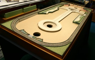
Please avoid dragging the Platform on rough surfaces as you may damage the finished wood base that surrounds the Platform. You will want to make sure your Platform always stays beautiful and treat it as if is a piece of valuable art because that is what it is. Figure 1 shows the Platform sitting on a 30”x72” adjustable table with some of the 20 pieces placed on it. The table is draped with a black cover cloth.
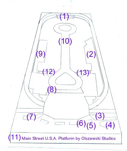
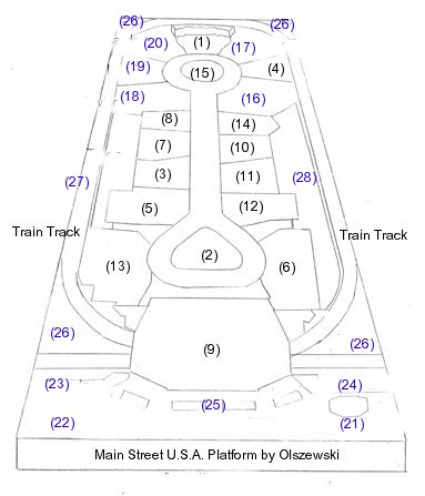
Figure 2 is a schematic we have prepared showing where the parts listed in Table 1 are to be placed and the recommended order of placement identified the 4th Column of Table 1 above. Later, Figure 4 shows the placement of each sculpture released to date for the Platform Base. The Main Street U.S.A. Road (10) and the Flower Bed Landscape pieces (2) and (9) are fixed to the Platform with several screws that need need to be removed. These screws were used solely for the transport of the Platform. Remove 3 screws from the Road (10) and set aside. Remove 2 screws each from the Flower Bed Landscape pieces (2) and (9) and set aside. Place 20 of the 100 rubber risers under the road before you place the Road (10) in the Platform. Set the other 80 risers aside as they will be used later when you are ready to place the buildings into the Platform. In your Platform package, you will find 5 Flower Bed Trees that will go in the Front Turn style Gateway area. The 3 middle trees can be glued into place, however leave the 2 outer trees loose as these will be replaced by smaller trees when the Newsstand and Stroller Rental/Will-call buildings become available in 2007. Figure 1. Main Street U.S.A. Platform
Figure 2. Platform Schematic
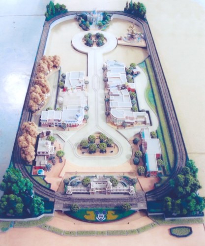
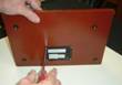
Instructions for Removing the Sculptures from their Wooden Bases After you have set up the Platform, you will now want to begin placing those sculptures you have collected on the Platform itself. Before you can do this, you will need to remove the sculpture from the wooden base that is attached to it. Figure 3 is a photograph of a partially filled Platform Base. Please note the trees at the corner of the photograph do not come with the Platform you received. Sets of the trees will be sold separately and their availability will be announced via email and purchase can be made on the Olszewski Studio web-site For Sale page. Figure 4 is a schematic showing the correct placement of the sculptures into the Platform. Figure 3 Partially Filled Platform
Figure 4 Platform Sculpture Placement Schematic
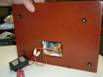
Each sculpture listed in the Table 2 below is mounted to a wooden base with screws and a small to medium size Phillips Head screwdriver is all that is needed to proceed to the next phase of setting up your Platform. Below are instructions and corresponding images to coincide to assist in removing the electrical part, the base, and placement of the risers (rubber feet), and the placement of the piece(s) in their proper places on the Platform.
Table 2. Main Street Platform Sculpture Placement Corresponding to Figure 4.
Click here for a larger view of the Images
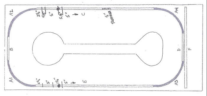
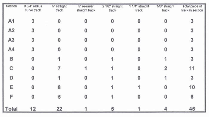
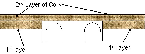
Train Track Installation InstructionsOlszewski Studios recommends installing the train track be spread over several days. We also recommend that you obtain a good reference guide on laying out train track for your platform. We used the following reference as our guide "Woodland Scenics - Scenery Manual" commonly found at your local hobby shop. The following instructions are here to help you in a general way in placing your working track in the Platform. It is also a good idea to lay your track into the Platform before loading the Platform with the Main Street buildings, other than the Train Station, which you need for train track placement. Other tools and materials you will need to install your train track include: Small Phillips Head Screw Driver White Glue Small hammer with punch Utility Knife or Pair of Scissors First Step is to carefully remove all fake track from the Platform by unscrewing screws with the small Phillips head screw driver. Second Step is to prepare to lay out the cork to create your roadbed. We have provided enough cork to form 2 layers. The cork is pre-cut to create a beveled edge. You should pull apart each piece and butt it together to form a new piece that has a beveled edge on each side. Make sure the widest side of the bevel is to the bottom. When laying out cork over the hole for the power supply, mark a dime size hole on cork and cut out with the utility knife or scissors. This will leave access to the hole for your power joiner when laying the track. When laying cork around the corners, you should use a utility knife or a good pair of scissors to snip 1/4" cuts on the outer edge of the cork every 1 to 2 inches. This will allow the cork to bend around the corner and still lie flat. Glue roadbed cork to platform and then 2nd layer to bottom layer of cork. Allow time for glue to dry before proceeding. Third Step takes place after the roadbed is security glued in place and now you can proceed to laying down track. We have broken down the track into 6 different track areas; please refer to the drawing at Figure 1.
Sections C & E are inter-changeable and you need to determine which side of the street you will want your train transformer to be on. Use the pattern from section C for the side you plan to put the train transformer on. Lay your track out on the roadbed and connect it all together. Make sure to attach the power wire joiners to the track and fish the wires down through the hole, before you begin to tack down your track. Run your train around the track to find areas that are not flat or seem to cause derailment. Make appropriate adjustments. Once the train is able to circle the track many times without problems, you should glue your track down to the roadbed. Allow time for the glue to dry and re-test your track by running the train around it. In Step Four, please refer to the reference manual to find instructions for this final step. This step will be the finishing of your track with ballast to make it look realistic. You will be able to find all the necessary items needed for this final step at your local hobby shop.
Train Track InstallationWritten by Bob Olszewski DAY ONE Placement of Train Station, Road and Sleeping Beauty’s Castle. First, you will want to unscrew the shipping screws that hold the Main Street Road and the side gardens on the Platform. Next, you will be looking to place the Train Station, the Main Street Road, and Sleeping Beauty's Castle in the Platform base.
Before applying glue for placement, check the heights of Train Station track bed to the left and right track beds. If the heights don’t match, adjust thickness by sanding the easy-to-sand balsa strips or use sheets of cardboard from a writing tablet to add height in small increments. Don’t glue in the Train Station until the layer one of cork is complete and track's position is checked. When checking heights, remember the Train Station track bed will only take one layer of cork, not two. This means that each end of the Train Station road bed should be even to one level of cork in the platform track bed. Cut a small piece of cork 1" long.
To check height of the Train Station track bed ends. The first layer of cork in the platform should be even with the Train Station track bed. DAY TWO Laying the First Layer of Cork. As previously mentioned, I am breaking this out in days as it is best to take your time and be patient during these steps. Trying to get too much done in one day will cause you to make mistakes. I have laid 4 sets of track in these units and have had the best success when I took my time and enjoyed getting the right results. Do the curves first. Start with the curve by the Sleeping Beauty's Castle. What you learn here will make the Train Station curve easier. Take one complete strip and lay the cork in the straight section directly behind the castle. Do not use glue yet. Take a pair of scissors and cut the cork every 1 ½ inches starting at the curve. Cut only to the center line. If a section falls out, you can glue it in later, once you are happy with the fit, it’s time to glue. If cut right, the cork should take the curve and lay down naturally. Mark with pencil in the track bed where the cork ends, so you can see where to end the glue. Remove the cork section and apply a generous amount of glue to the track bed. Brush out the glue so it is evenly spread over the entire surface with the glue evened out, lay-in the cork section plus any of the small units that may have fallen off. Keep the cork in the center of the track bed with an even amount of empty space on each side. For extra clearance for trees, the platform track bed is wider than the cork. It is not necessary to have the platform road bed completely filled with cork. Later, the ballast or gravel will cover the openings where the cork does not cover. Next, do the curve next to the train station. The first layer of cork will fit right up to the train station track bed but will not cover it. With the train station set in, but not glued in, cut the cork angle so the cork fits up against the train station track bed. Cut the 1 ½ splices to take the curves and check for fit. Mark the end of the cork strip to show where you should end the glue. Once you are satisfied with the fit, brush out a generous amount of glue in the platform track bed. Do not glue cork to train station edge. It might be a good time to check the castle and cork for any lifts and if you find any lifts just add more glue. Laying in the cork between the curves. When adding in the straight lengths between the curves trim the ends of the cork so the angles match the curves already in. The fit should be tight. Before gluing, mark the place where the power unit hole locations are, when gluing, add some glue to the ends of the cork that connects to the curve endings. If the cork lifts where the ends meet, put a small piece of scotch tape to connect them together. Next, lay in the cork in the straight area in front of the train station. Make sure that the cork does not hang out over the edges. Once all cork is glued in, keep checking for any lifts and make corrections. When the first cork layer is in, let dry until the next day.
DAY THREE Time to check the track and glue Train Station in Place. Find mark you made for the power line and cut a small hole, to fit the wires through. Cut the hole as small as possible. If the hole is too large, you will need to plug it later so gravel doesn't’ fall through. Time to check the track. Assemble the track, and lay track in track bed.
Once the track is assembled and in the track bed, take a box car and set it on the rails and push it past the station. This simple check will assure you that you can move ahead and glue the station in place. For your information, besides providing a road bed, the purpose of the cork is to absorb the sound of the engine so it runs quietly. Running the same engine on a piece of plywood without the cork would make for a noisy unit. Because the cork is so easy to work with, any mistakes you feel you have made can easily be corrected. Just fill in any mistakes with scrap pieces of wood, so relax and have fun and enjoy yourself.
DAY FOUR Remove the track and Complete 2nd Layer of Cork. Follow the same sequence you did on the first layer of cork. Curves first, then straight. When you lay in the curve over the train station, the process will be the same but you will need to remove two small sections of cork to fit around the fake gravel on the right and left side of the train station. Do this by laying in the straight section. First, mark the cuts with a pen, remove the 2 sections and proceed to cut the curve with 1 ½ “ spaces. Lay in the cork and make any adjustments before applying glue. Don’t forget to mark the dot for the power supply lines.
DAY FIVE Laying Track - Be Patient and take your time! Cut power line hole and place power lines down through the hole and to the outside of base. Even though the track is only connected with track connectors and not nailed to cork, you should be able to do a first test run to check for placement as close to center of track bed and check to make certain cars miss the train station over hang. Front Straight Track. What you do with the front straight track section will be based on whether you intend to connect this section to another layout. The straight track section was included and extended so a larger layout could be added. If you intend yourself to actually run cars on the straight track section, you will need to make some modifications to the railroad ties. This is necessary so an engine and box car can make it past the trees. The modification needed is as follows: Assemble the entire length of track and lay on cork so the track is centered right and left. On the end of the train station track bed you will see two fake gravel sections at each end. Cut the railroad ties that are next to these units so the track can shift toward the train station. This extra shift will allow enough room for an engine and cars to make it bypass the trees. If you do not intend to ever actually use this section, then just lay in straight track in nail in place. Once you are satisfied with the track placement you can begin to nail down the track to the cork. We have used standard industry materials when possible, but we were not able to find track nails shorter than the ones provided. Because the road bed is a hard resin, the nails will not go into the resin surface and will set too high on the surface of the plastic railroad ties causing the train to sop. To overcome this we have two choices:
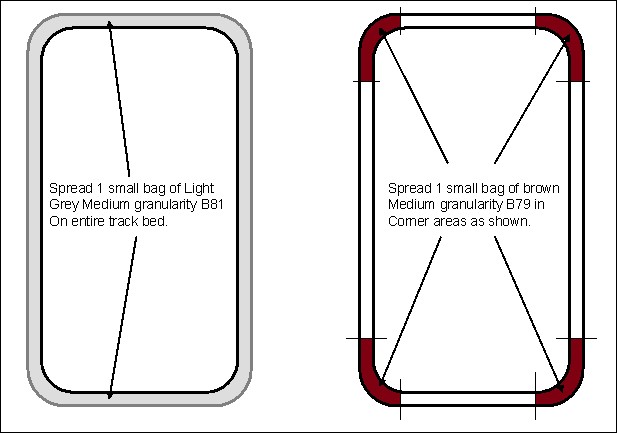
Once you cut a few of these it will get easier. To set the track placement, nail down only lengths of 12” apart. Run the train and look for problem areas. Track laying will require the most patience. To test your track, run the engine with one or two box cars on it. As the train travels around, the problem areas will become obvious. Now is the time to make adjustments looking for these kinds of problems. Run your finger over the rails to feel for uneven and sharp rail edges. If the trail connector is not properly installed you will feel one rail higher than the other. Make certain rails are flush with no space between them where sections meet. A space between the sections will derail the train. Watch the train with your eye at rail level. A dip in the track will cause the engine to work harder or uncouple the box cars. Use the same cardboard from tablet backs to incrementally raise low sections. Remember, the gravel will cover any cork or cardboard shims you will add. Once you are satisfied with how the train runs, proceed to add the remaining nails to the railroad ties, keep running the engine and one car as you go along in case any new problems occur. Note that The nails for the railroad ties in front of the train station will need to be cut to a one cork thickness, not a two-cork thickness. Once the track is completely nailed in place and tested, a tiny spot of super glue could be applied to the edge of the railroad ties and to the nail heads. Be extremely careful not to get glue on the metal rail lines. This final spot gluing will secure the track placement and ready the track for the next step. Let the unit dry for 1 day before testing with the engine and box cars again. If the test goes well, you are ready to add the ballast. Ballast. (This will take more than one day) and to do ballasts properly, we suggest you refer to Woodland Scenic's - Scenery Manual. As an artistic recommendation, use the smallest rock size or ballast size you can find. Also you should look at the colors available and mix your own color combination. We have provided a color image of the ballast Olszewski used in the Platform that is on display at the Disney Gallery above the Pirates of the Caribbean Attraction. The travel or ballast at the park appears to be a gray rock. You can purchase a straight gray rock and lay in dry section to see how it looks. Use a vacuum to remove it before you go on to the final application. To do this properly it is imperative that you follow the instructions completely as outlined in the book. Covering the track with masking tape is a must and will take a long time. Do it right and take your time. The book should take you to completion. In addition, Bob has created the following instructions to help. Disneyland Ballast Instructions Day 1:
Day 2:
Doing this will take some time but you will have a project you will be very proud of, especially as you add your own individual custom accents. People may ask why we chose this particular track approach as it is fairly complex to install. Atlas was the only company that made a 9 ¾ radius curve that could fit a 30” table width. If we had used a snap track 11” radius, the width of the unit would have increased substantially and would not have been as compact. Caution: NEVER use steel wool to clean your track. Rubber track cleaning tools are inexpensive and readily available at all train stores. Clean regularly to remove engine oils from the track to assure consistent high performance from your engine. Power Hook Up. Collectors should be aware that the power lines enclosed in our electrical kit are designed for all standard train transformers. The transformer that came with your train was designed for a different track system but it can easily be adapted to fit your layout. Simply trim ½ inch of plastic from both power lines to expose ½ inch of wire. Twist each wire separately to increase the wires strength. Bend wire back in a U-shaped loop and insert each loop into the black tab on the wires of your transformer. Tape to hold in place. This simple adaptation will save you the purchase of a new transformer as the transformer you already own is adequate to do the job you need.
CARING FOR ACRYLITE (Plexiglass) Cover WASHING Wash the cover with a solution of mild soap and lukewarm water or the sample of plastic cleaner provided with your order. Use a clean soft cloth, applying only light pressure. Rinse with clean water and dry by blotting with a damp cloth or chamois. Grease, oil or tar may be removed with a good grade of hexane, aliphatic naphtha, or kerosene. These solvents may be obtained at a paint or hardware store and should be used in accordance with manufacturers recommendations. Any oily film left behind by solvents should be removed immediately by washing.
DUSTING Dust with a soft damp cloth or chamois. Dry to gritty cloths may cause surface scratches and create a static electric charge on the surface (see section on neutralizing static electricity). POLISHING Protect ACRYLITE and maintain its surface gloss by occasional polishing with a good plastic cleaner and polish or auto past wax. Apply a thin, even coat with a soft clean cloth and polish lightly with cotton flannel. Then, wipe with a damp cloth to help eliminate electrostatic charges which can attract dust particles. NEUTRALIZING STATIC ELECTRICITY A static electrical charge can develop on ACRYLITE sheet but is common to many materials,, particularly plastics. When the paper or film masking is stripped off the acrylic sheet, a static charge is created on the sheet surface. Static electricity attracts dust, chips, etc. floating in the air or on nearby work surfaces and holds these contaminants tightly to the surface. A compressed air gun will remove some of this surface direct, but much of it continues to cling to the sheet. Because the sheet must be direct-free before bending, painting or thermoforming operations, a separate step is required. To eliminate the electrical charge on all plastic surfaces, ionizing air guns can be used. These guns provide a stream of compressed air containing low levels of alpha particles. The alpha particles are harmless to the operator, but they effectively neutralize static charges which hold dirt to the surface. By using ionizing air to clean ACRYLITE sheet after the masking has been removed, the sheet can be directly heated, painted or otherwise processed. Because additional cleaning is eliminated considerable man hours will be saved. The economic advantages are obvious. The appearance of painted and/or silk screened sheet is greatly improved by the elimination of static charges. Several anti-static cleaners for plastics are also available which will reduce static electricity and dust attraction. Wiping with a soft damp cloth or chamois is all that is necessary to keep ACRYLITE sheet dust-free between applications of these cleaners. REMOVING SCRATCHES Fine scratches can be removed by hand polishing. Apply a plastic scratch remover or a compound such as Simonize cleaner to a soft flannel pad and rub. When the scratches have disappeared, remove all residue and polish. For deeper scratches, first sand lightly with a 400-grit "wet or dry" sandpaper, using plenty of water an rinsing the sandpaper frequently. Follow- by buffing with a clean muslin wheel and a good polishing compound. For the highest gloss, use a clean-up wheel made of soft cotton or flannel sections, and on which no compound is used. An electrical drill with a buffing wheel also is ideal. Contact American Plastics Corporation at 1-800-448-2234 on available scratch removal kits. |
||||||||||||||||||||||||||||||||||||||||||||||||||||||||||||||||||||||||||||||||||||||||||||||||||||||||||||||||||||||||||||||||||||||||||||||||||||


All figurines and displays are copyrighted by ©Disney, ©Goebel Miniatures, and ©Olszewski Studios
info@olszewskistudios.com
Web Design By Moe Technologies, Inc.